Thursday, 31 March 2022
Wednesday, 30 March 2022
Tuesday, 29 March 2022
Monday, 28 March 2022
Connecting Shapes in Microsoft Visio
BASIC
DIAGRAMS
Several shapes are positioned onto the drawing canvas.
When you drop the shape on the grid it will snap to the nearest grid line.
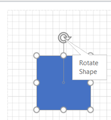
The white circles facilitate size changes; the small circle at the top of each shape provides rotation options.
When the connector tool is activated shapes display connection points when the mouse hovers over the shape.
Some of the shapes will have yellow circles (Control handles) these have distinctive
features for each shape. If you hold
your mouse over the shape, you will see a text box description as shown below.
If you want to move several shapes in one go, you can use
your shift key to select each shape or drag over them with your mouse and then
move them as a group.
There are two types of shapes, one-dimensional and two-dimensional as shown below.
CONNECTING
SHAPES
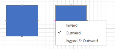
There are three main types of connector in Visio, Inward, Outward and Inward/Outward.
Inward connectors:
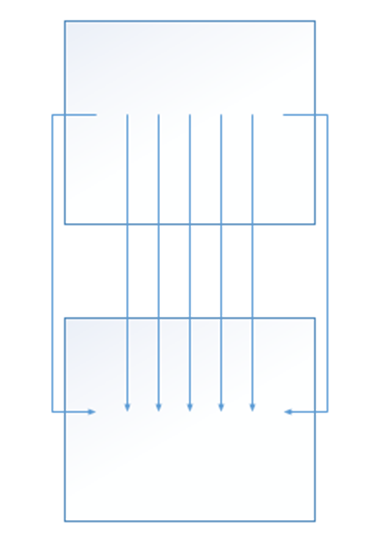
Most shapes have inward connection points, which means that
you can glue connectors or other shapes with Outward connectors to them. (Black
Squares)
Outward Connectors:
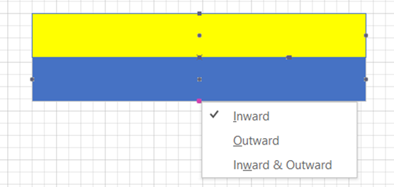
A 2-D shape with an Outward connection point can be glued to another 2-D shape with an Inward connection point. Right click on the connection point to change the type. Firstly, activate the Connection Tool.
Once the connector is changed it will glue to the Inward
connector on the other shape and move as one.
Inward/Outward Connector
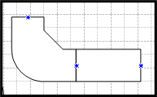
When you create your own shapes, you can set their connection
point type.
Use inward connection points in drawings that use connectors (connector: Any
one-dimensional (1-D) shape that can be glued between two shapes in a drawing
to connect the shapes.) to connect shapes, such as flowchart
diagrams.
Use inward or outward connection points when you want to glue 2-D shapes together in a particular direction or order. For example, in an office layout diagram, if you want outlet shapes to be attracted to walls:
Set
the outlet shape to have an outward connection point.
Add
inward connection points to the Wall shape (perhaps spaced according to
electrical wiring code).
Use inward/outward connection points to allow shapes to be
glued together in any order. For example, if you have a wall shape with
inward/outward connection points, it won't matter which wall segment you drag
first; it will always glue to another shape. However, if you have an outward
connection point on one end of the wall and an inward connection point on the
other end, you will need to drag the outward end to an inward end to glue the
walls together.
There are two types of glue in Visio
Shape to Shape and Point to Point
Shape to Shape
With shape-to-shape glue (also known as dynamic or
"walking" glue), a connector stays glued to shapes by moving to the
closest available connection points as the shape is repositioned.
Point to Point
With point-to-point glue (also known as static glue), a
connector stays glued to its specific connection point on each shape when you
reposition the shapes.
A shape's connection point turns red when you glue a connector
to a specific point on a shape.
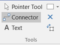
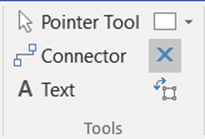
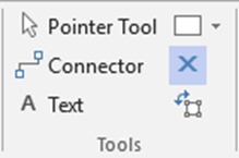
To create a shape-to-shape connector, click the connector
tool on the toolbar.
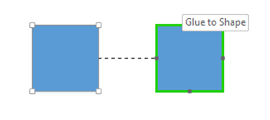
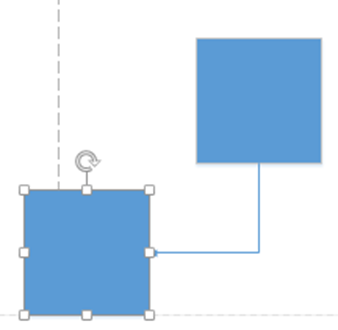
Drag the first shape into position and leave it selected then drag the second shape into position. The connector will snap into place.
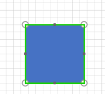
Shape – To – Shape the outline on the boxes turn green as
you float over them (not over a connection point).
When the shape is moved the connector moves to the nearest point.
Point-to-Point connections
Click the connector tool and hover over the first shape
until the connection point is highlighted, then drag to the other shapes
connector point.
If you move either of the shapes, the connection will be
glued to the
original position.
Although shapes have pre-set connection points, you can add additional connection points by selecting the connection tool.
Hold the Control Key down and click on the shape to apply
the new connection point or points.
You can use the connector tool to join the new connection
points as shown above.
Courses
Saving a Template in Microsoft Project
Templates
in Microsoft Project
Saving a
template in Microsoft Project, saves time, focusses teams and keeps plans
standard. Templates in Project are stored in either the personal templates
folder or a network folder. Use Project options to change folder location.
Template
setup
Design
the task list and add the links. Embed any external documents. Once the task
list and links are sorted you can format the Gantt chart to display as
required.
Resources
Add
resources as normal to the resource sheet. Select the Assign resource feature
to allocate resources for each task. Do not overallocate resources. Any
resource displaying a red symbol is over allocated.
Reports
Creating
a template report saves time and standardises reporting.
Custom
Fields
Add
custom fields to the Gantt chart table or create a new table with the custom
fields.
Saving a
Template
When all
elements of the template are complete, select Save from the menu.
In the save as dialogue box, select the template option. Navigate to the
template folder indicated in project options and save. To use the template,
select file and new.
Templates
sit in either the personal folder or a network folder both are shown in Project
options..
Courses
Search
for courses here
Search
for online courses here
There are
three course formats. The first format is, one to one, this is a tailored
session covering topics selected by the student. The second format is Classroom
based courses, this is a structured session. Online, this course follows the
format of either of the other two.


